Consumer Electronics / Fitness Wearables
Wireless EMG Wearable: Muscle-Activity Sensor with ADS1292, nRF54L15 and nPM1300
For a fitness-wearable company we designed the electronics of a slim wireless surface-EMG sensor: ADS1292 front-end, nRF54L15 BLE module, nPM1300 PMIC and a BMI270 IMU. Status: Rev A1 schematics and BOM delivered in June 2026; prototype build next.
Fitness-wearable product companyRev A0–A1 schematics: 2026Rapid Circuitry electrical engineering
Published Last reviewed:
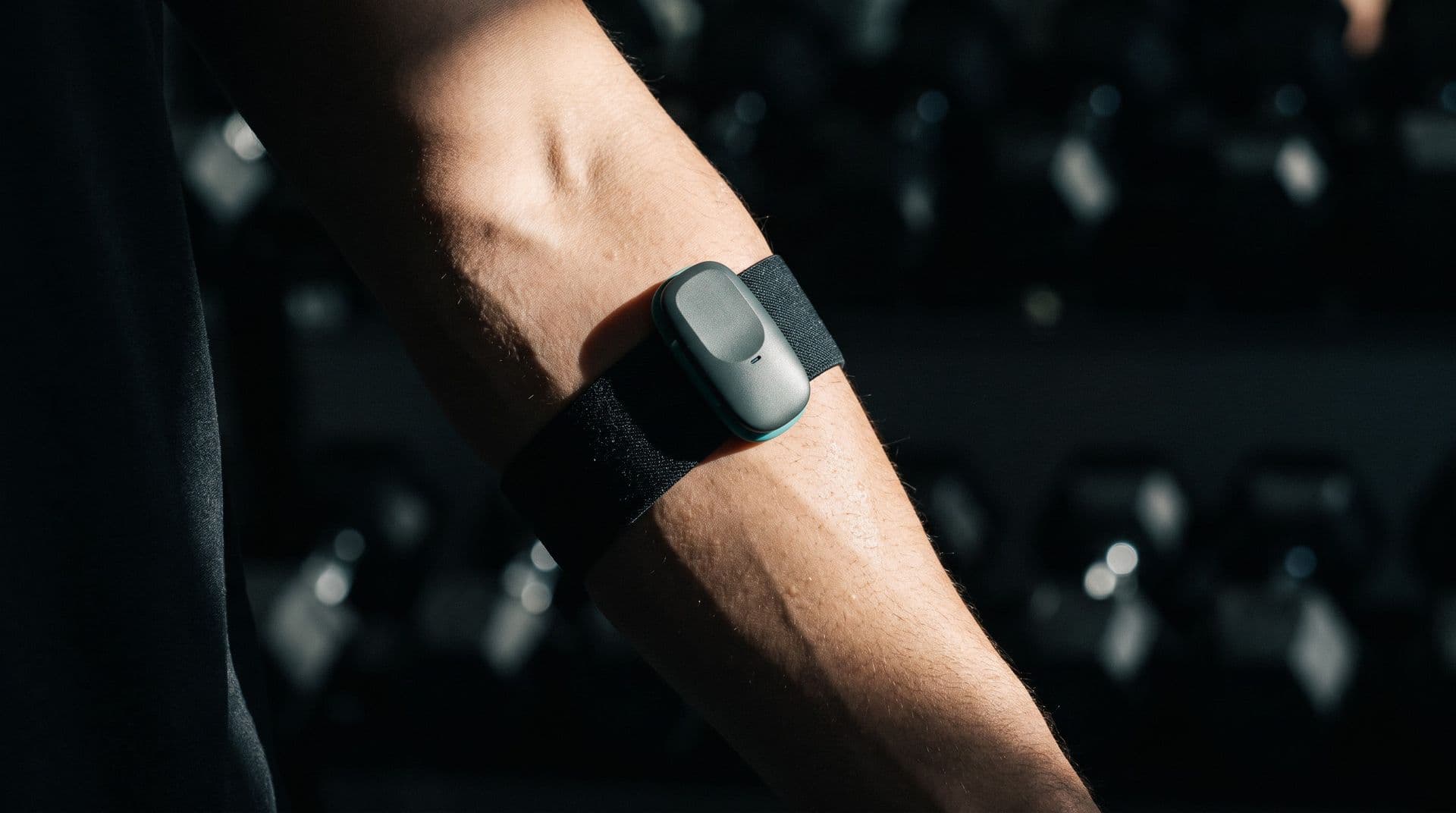 Illustrative image
The Challenge
The client wanted a small wearable that measures muscle activity during training and streams it over Bluetooth. It had to charge over USB-C, update its firmware wirelessly and keep the analog front-end quiet next to the radio, all inside a narrow enclosure the client had already designed.
Clean EMG from snap electrodes
Fitness users place the sensor themselves on three Ag/AgCl snap electrodes, so the front-end must cope with varying contact and motion.
Impact: 1 differential channel + referenceTight board outline
The enclosure was already designed, which fixed a long, narrow board with little room for power, radio and sensors.
Impact: Existing enclosure CADNo USB on the MCU
The nRF54L15 has no USB peripheral, so firmware updates and charging had to be handled without a USB data path.
Impact: BLE-only firmware updatesQuiet analog next to a radio
The EMG front-end shares a small board with BLE, a PMIC and an IMU, so its supply had to be isolated and switchable.
Impact: Gated analog railOur Solution
We defined the architecture (Rev A0), then refined the EMG front-end to Rev A1 (confirmed in June 2026), and delivered net-level hardware documentation with every pin checked against the manufacturer datasheets.
System Architecture
A single-channel EMG sensor with motion data and Bluetooth streaming.
EMG front-end
- TI ADS1292, channel 1 differential; channel 2 powered down
- Right-leg drive to the reference electrode
- Fitness-class RLD protection resistor (100 kΩ)
- DC-coupled input, gain 6, 1000 SPS
- Three Ag/AgCl snap electrodes in a 25 mm triangle
Processing and radio
- nRF54L15 BLE module, external-antenna variant
- Bosch BMI270 IMU on the shared SPI bus, own chip-select
- IMU interrupt used for motion wake
- Firmware updates over BLE
Power
- Nordic nPM1300 PMIC with charger
- USB-C charge-only; CC pins straight to the PMIC
- 1.8 V buck as the single logic domain
- 3.0 V buck through a load switch as the gated analog rail
- ~300 mAh LiPo, 200 mA charge current
Key Parts
| EMG front-end | TI ADS1292 |
| BLE module | nRF54L15-based module |
| PMIC / charger | Nordic nPM1300 |
| IMU | Bosch BMI270 |
| Logic rail | 1.8 V (single domain) |
| Analog rail | 3.0 V, load-switch gated |
| Charging | USB-C, charge-only |
What We Delivered
- Hardware design document with net-level pin tables
- Pinouts verified against the manufacturer datasheets
- Block diagram schematic sheet
- Power and charging schematic sheet
- EMG front-end schematic (Rev A1) with design notes
- MCU, BLE and IMU schematic sheet
- Bill of materials
Key Engineering Decisions
What we chose, and why.
One logic voltage
MCU, IMU and ADC digital side all at 1.8 V
No level shifters on the shared SPI bus
Fewer parts on a narrow board
Gated analog supply
3.0 V rail behind a load switch
Front-end can be fully powered down
Keeps radio noise off the EMG input
Fitness-class protection
100 kΩ RLD resistor, DC-coupled input
Chosen for a consumer fitness device
Not a medical-grade isolation design
Catch the gain-code trap
ADS1292 PGA field: code 000 means gain 6
Channel register set to 0x00 for gain 6
An earlier calculation note had it wrong; flagged
Outcome and Status
Rev A1 schematics, design documentation and the BOM were delivered in June 2026. No prototype measurements are reported here because the prototype build was the next step. Remaining open items were the exact battery part and the LED style.
Schematic revision
Rev A1
EMG front-end revision confirmed in June 2026
Documentation
4 sheets
Block diagram, power, EMG front-end and MCU/BLE/IMU, plus BOM
Pin verification
Datasheet-checked
Every net-level pin table checked against the manufacturer datasheet
Technologies Used
Related Case Studies
Healthcare / Prosthetics / Biosignal
EMG Sensor Front-End: Low-Noise Myoelectric Electrode Design for Bionic-Hand Control
Healthcare / Neurotech / Wearables