Robotics / Prosthetics / Motor Control
Dexterous Robotic Hand: 6-DOF Motor-Control Electronics with Faulhaber Micromotors and STM32G4
For an Indian prosthetics company we defined the control electronics of a battery-powered 6-DOF dexterous hand: six Faulhaber micromotors with 4096-line encoders on an STM32G4. Status: architecture and MCU pin-mux complete (2026); board design next.
Indian prosthetics companyArchitecture phase: 2026Rapid Circuitry hardware team
Published Last reviewed:
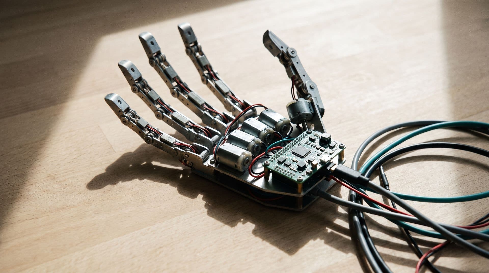 Illustrative image
The Challenge
A dexterous prosthetic hand has to drive six small motors precisely, sense grip force, and run all day from a battery inside a palm-sized space. The client needed the actuator stack and the electronics architecture fixed before board design: which motors, which encoders, which drivers and microcontroller, and how to power them from a small pack.
Six axes, one small MCU
Each axis has a quadrature encoder, but typical small MCUs have only a few hardware encoder timers. Counting all six in software at full speed is not reliable.
Impact: 6 encoder channels neededForce and current sensing
Grip force is inferred from motor current, so every driver needs a clean current-sense path the MCU can sample.
Impact: Per-motor current feedbackMixed voltages from one battery
The motors, encoders and logic want different rails (6 V motors, 5 V encoders, 3.3 V logic) from a compact battery pack.
Impact: Three rails from one packSingle-vendor preference
The client preferred a single-vendor electronics BOM (STMicroelectronics) for sourcing, which limits the choice of chargers, gauges and PMICs.
Impact: ST-centric BOMOur Solution
We selected the actuators and encoders from the manufacturer's current datasheets, researched and cross-checked motor drivers and microcontrollers against primary datasheets, and produced a conflict-free STM32G474 pin-mux. The power architecture is now being re-based on the two-cell pack and ST-sourced BOM the client chose.
System Architecture
Six brushed DC micromotors with encoders, driven and sensed from one STM32G4 in the palm.
Actuation
- 5× Faulhaber 1228 SXR (4.5 V winding) on the five flexion axes
- 1× Faulhaber 1024 SR (6 V) on the thumb swivel
- Faulhaber IEP3-4096 magnetic encoders on all six axes
- Approved encoder cable and connector options
Control and sensing
- STM32G4 (Cortex-M4F, 170 MHz); initial pick STM32G473VEH6
- Native quadrature-encoder timers plus SPI quadrature counters for the extra axes
- Brushed DC H-bridge drivers with integrated current mirror for grip force
- Conflict-free pin-mux generated and checked in STM32CubeMX
Power
- 2S LiPo pack
- 6 V motor rail, 5 V encoder rail, 3.3 V logic rail
- Two-cell option: ST buck converters (L6986 class)
- Charger, protection and fuel gauge must match the cell count
Key Parts
| Finger motors | 5× Faulhaber 1228 SXR, 4.5 V |
| Thumb swivel | Faulhaber 1024 SR, 6 V |
| Encoders | 6× Faulhaber IEP3-4096 |
| Microcontroller | STM32G4 family (G473/G474) |
| Extra encoder inputs | SPI quadrature counters (e.g. LS7366R) |
| Drivers evaluated | TI DRV8231A / DRV8251A / DRV8235 |
| Battery | 2S LiPo |
What We Delivered
- Actuator and encoder specification from the manufacturer's current datasheets
- Motor-driver and MCU research with every key figure checked in primary datasheets
- Conflict-free STM32G474 pin-mux (LQFP100) with alternate functions verified
- Power-tree options for one-cell and two-cell packs
- Power-architecture update for a two-cell pack and an ST-sourced BOM (in progress)
Key Engineering Decisions
What we chose, and why.
Count encoders in hardware
The STM32G474 has four native quadrature timers
Axes five and six use SPI quadrature counters
No missed counts at full motor speed
Current sense in the driver
Drivers with an integrated current mirror
One ADC channel per motor for grip-force estimation
INA240 / INA181 shunt amplifiers kept as an option
Cell count drives the power tree
ST's single-chip charger, gauge and PMIC parts are single-cell only
A two-cell pack needs bucks and a different gauge arrangement
We flagged this before the pack was chosen
Keep the 4.5 V finger winding
A 6 V winding was offered as an alternative
The client kept the 4.5 V winding
Rails and driver limits set to match
Outcome and Status
The actuator stack, encoder choice, microcontroller, driver options and pin-mux are defined, and the power architecture is being re-based on a two-cell pack. Board design and hardware bring-up are the next steps, so no measured performance is reported here.
Axes specified
6
Five flexion axes plus thumb swivel, each with a 4096-line encoder
Pin-mux
Conflict-free
STM32G474 LQFP100 alternate-function map checked in CubeMX
Next step
Board design
Schematic and layout of the palm control board
Technologies Used
Related Case Studies
Healthcare / Prosthetics / Biosignal
EMG Sensor Front-End: Low-Noise Myoelectric Electrode Design for Bionic-Hand Control
Robotics / Motor Control